Plane wave's transmission in a substate structure and its theoretical realization in COMSOL
Plane wave’s transmission in a substate structure and its theoretical realization in COMSOL
Date:
Create at: 2020 02 20
Update at: 2020 08 20
Introduction
In quantum nano optics, we often encounter this kind of problem:
Simulating the scattering of light by a nano objects on substrate.
The best way to simulate this kind of problem is the background field method since the enhancement of the light can be easily obtained. I use COMSOL to simulate this kind of problem and the simulation would be much faster if the background field is set via theoretical expression. The numerical implementation can be found in another notes
A_En_PlaneWaveInputDirectionsViaPort/#Explanation-of-the-incident-angle.md
This note will firstly derive the theoretical expressions of the transmission properties and then introduce its implementation in COMSOL.
Theoretical derivations
The Chinese version of this derivations can be found in
I will derive the transmission and reflection of plane waves in a two medium interface.
Boundary conditions and properties of plane wave
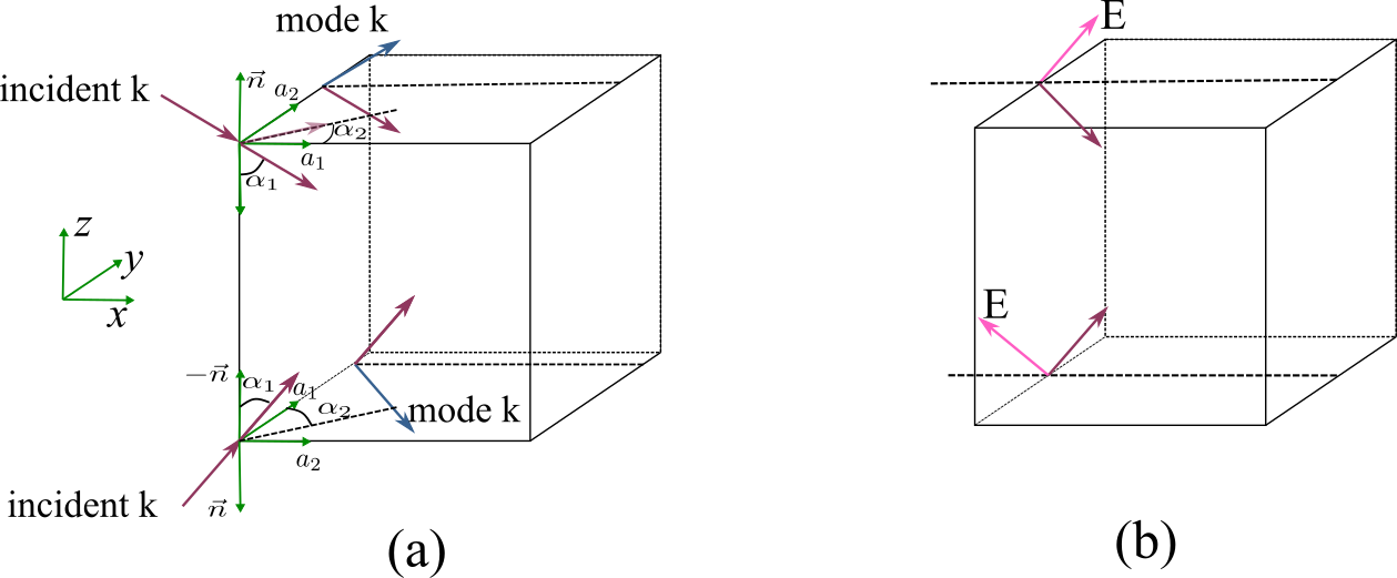
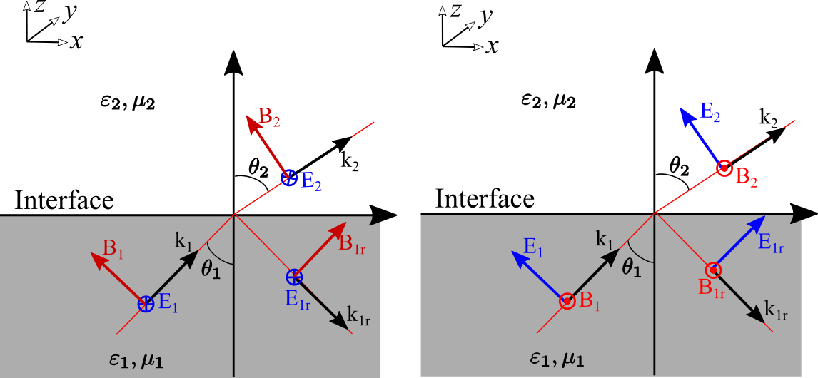
For any plane wave, when it is transmitted and reflected on the surface of the medium, due to the difference between its polarization direction and the direction of the incident surface, it can be discussed in two cases
- S polarization, the electric field is perpendicular to the incident plane, as shown in the left picture below
- P polarization, the electric field is parallel to the incident surface, as shown in the right picture below
Pay attention to the positive direction of the figure below. Because of different definitions, the final expression will have a difference in sign. All my next derivations are based on the following figure.
That is to say, any plane wave $\boldsymbol{E}$ can be written as a combination of S polarization and P polarization
We assume that a plane wave is incident from medium 1 to medium 2. We stipulate that the direction of $\boldsymbol{n}$ is from medium 2 to medium 1. The electric and magnetic fields need to meet the corresponding boundary conditions
According to the definition shown in the figure above, we can decompose the field and wave vector separately. Whether it is P polarization or S polarization, the wave vector can be written as
The horizontal wave vector $(k_x,k_y)$ is continuous, and a horizontal wave number can be defined
In order to obtain the reflection and transmission properties of the geomagnetic field, we need to analyze it according to the boundary conditions. We define the incident electric field in medium 1 as
In addition, what needs to be emphasized is the definition of refractive index and the definition of speed. The propagation speed of a plane wave in a medium is
That is, the refractive index can be expressed as
For a plane wave, the relationship between its electric field and magnetic field is
The power density of a plane wave can be expressed as
The average power density can be expressed as
S Polarization
For S polarization, first, the tangential component of the electric field $\boldsymbol{E}$ is continuous
Then the tangential component of the magnetic field $H$ is continuous
According to the relationship between electric field and magnetic field $E=B\nu=Bc/n$, (note that $n=c/\sqrt{\varepsilon\mu}$) we can convert the relationship between the magnetic field into the relationship between the electric field
Comprehensively available, the last relationship between $E{1},E{1r},E_{1t}$
The above expression can be further transformed into the form of wave vector representation, because $k{z1}=k{1}\sin(\theta{1}),k{z2}=k{2}\sin(\ theta{2})$, therefore
P Polarization
For P polarization, the tangential electric field is continuous, that is
Then the magnetic field is tangentially continuous
Further conversion
Comprehensively available, the last relationship between $E{1},E{1r},E_{1t}$
The above expression can be further transformed into the form of wave vector representation, because $k{z1}=k{1}\sin(\theta{1}),k{z2}=k{2}\sin(\theta {2})$, and $k{1}=k{0}n{1},k{2}=k{0}n{2}$, so
Following the same transformation, we can get
This result is consistent with the book Principle of Nano Optics. As a result, this derivation made me more familiar with the so-called Ferrell formula. It should be noted that our derivations are based on specific graphs, and different graphs will have different symbols.
Nonetheless, be aware that the literature is not standardized, and all possible sign variations have been labeled the Fresnel Equations. To avoid confusion they must be related to the specific field directions from which they were derived.
Special case: non-Magnetic material
In reality, the magnetism of most materials can be ignored. We think that $\mu{1}=\mu{2}$, so
Special case-normal incidence
S and P polarization will be the same at normal incidence. For the sake of simplicity, we think that $\mu{1}=\mu{2}$, we can verify that the normal incidence is $\theta{1}=\theta{2 }=0$, at this time
We find that the reflection of s-polarization and p-polarization happens to have a negative sign, which is different from the definition of the positive direction of the electric field with s- and p-polarization.
- For s polarization, it should be $E+E_{r}^{s}$
- For p polarization should be $E-E_{r}^{s}$
Special case: total reflection
According to the Fresnel formula,
Considering $n{1}>n{2}$, at this time $\theta{1}<\theta{2}$, increasing the incident angle continuously, there will be an angle that makes the transmission angle equal to 90 degrees, which is generally It is called the critical angle, $\theta{c}=\arcsin(\frac{n{1}}{n_{2}})$. If you continue to increase the angle, the wave passing through the interface will decay exponentially along the z direction.
although there must be a transmitted wave, it cannot, on the average, carry energy across the boundary.
Let’s analyze the specific physical process of light and then total reflection. The previous transmission and reflection coefficients are further expressed as
In $\theta{1}\ge\theta{c}$, there is an imaginary number in the radical. In this case, the numerator and denominator of the reflection coefficient is just a complex conjugate difference, but the square of the modulus is equal to 1. That is, all the energy is actually reflected at this time. Of course, this does not mean that there is no energy passing through the interface, but it is attenuated in a short distance after passing through. We can write the transmitted wave as
Among them, $\boldsymbol{k}{2}\cdot \boldsymbol{r}=k{2x}x+k{2z}z=k{2}\sin\theta{2}+k{2}\cos \theta_{2}$, according to Fresnel’s law
而
That is, the final field can be expressed as
Among them, for the sign of $\pm$, the final field must be attenuated, that is, $-$.
COMSOL implementation
The previous is the basic derivation, the analytical expression of the theory, this section will derive how to set it in COMSOL. When setting up COMSOL, you need to pay attention to the following points
- The field in COMSOL is expressed as $e^{i\omega t-i\boldsymbol{k}\boldsymbol{r}}$, so when setting the field expression in space, the wave vector related to the exponential term must be taken as the complex conjugate . For example, we normally have an imaginary number $a=\sqrt{-1}=i$, but it should be taken as $a=\sqrt{-1}=-i$ when setting COMSOL expressions.
- In COMSOL, Ex, Ey, and Ez are set separately. Pay attention to the positive direction of the coordinate axis, and pay attention to the conversion from the previous schematic diagram to the specific COMSOL coordinates.
Scatter on Substrate Example analysis
I think this example can be analyzed in more detail in the follow-up. Here I will briefly describe the information that this example can give us. This example was originally intended to allow us to save of theoretical setting and directly calculate the background field numerically. In the old version of COMSOL5.1, there is no evaluation angle and Azimuthal angle to define the incident angle. We can see the definition process from the example Scatter on Substrate, as shown in the following figure
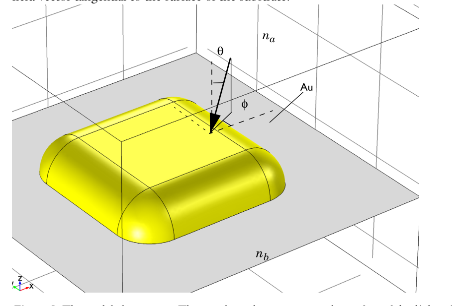
A beam of horizontally polarized light strikes from above, so the incident wave is not necessarily a plane wave. The expression for its electric field is written as
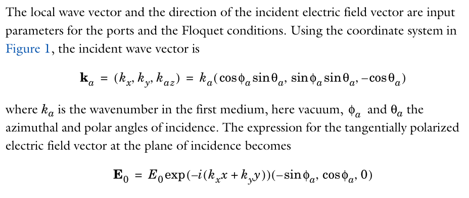
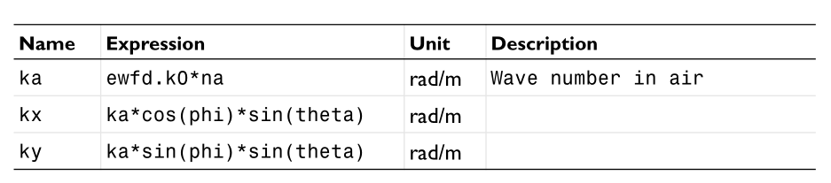
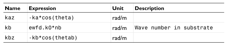
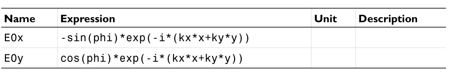
We can see from the above expression how to turn the analytical expression into an example in COMSOL. Because it is incident from top to bottom, that is, incident along the -z direction, so kz are all negative numbers. This example only sets a field in the port plane. In practice, what we need to set is the background field in the three-dimensional space, which will also participate in the z coordinate.
Plane wave vertical incidence setting
The second thing to talk about is the incidence of plane waves from bottom to top, with glass below and air above. This model is used to calculate that in Wang Zhiyuan’s experiment, light is incident vertically on the glass, and there are gold nanoparticles on the glass. The model has multiple calculation methods
- Calculate the background field numerically, and then use the numerical background field to solve the scattered field
- Write out the background field theoretically, and then numerically solve the scattered field
- Do not use background field and scattered field, direct plane wave incidence to solve the total field, but need to calculate whether there are two cases of gold nanoparticles.
I finally chose the second one. The advantage is that the background field is analytically accurate. The disadvantage is that the background field needs to be calculated manually, various parameters need to be calculated, and a thorough understanding of the properties of reflection and transmission is required. The following are some settings when calculating.


As you can see, I set it according to the s-polarized incident mode. Therefore, the incident and reflected fields of the Ex field are directly added. This is very important, because what I want to calculate next is the setting method of p-polarization.
P-polarized plane waves are incident obliquely along the positive x-axis
Analytical expression
This is to calculate the oblique incidence. When we set it specifically, SiO2 is on the bottom, and the plane wave is incident from the bottom to the top, from the negative X direction to the positive direction, that is, the polarization is in the X-Z plane. Then correspondingly, the incident wave in this coordinate system should be written as,
Note that the $k_{z}$ of the reflected light should become a negative sign, and the relationship between the projected field and the reflected field is
In the glass layer, the total field is the superposition of the incident field and the reflected field, and the sign of different components needs to be considered when superposing.
In the air layer, the total field is the transmitted field
COMSOL Settings Summary
I have encountered a lot of pitfalls in COMSOL settings. Here are the things to pay attention to.
- The phase expression used by COMSOL is $e^{i\omega t-ikx}$, so the first is a change in the expression.
- In addition to setting this item to a negative sign, special attention should be paid to the presence of imaginary numbers. For example, if the wave vector on the exponent has an imaginary part, add a negative sign to the imaginary number, such as $kz=1+i$. The imaginary part usually means loss, but it is an exponential increase in COMSOL. We need to take the corresponding complex conjugate.
- Since the transmission and reflection coefficients also contain $\cos\theta=k_z/k$, the complex conjugate must also be taken! ! !
- Because it is total reflection, the transmission angle is a complex number. Generally, for complex numbers, we have a method, $\sqrt{-1}=i$. When the sphere transmission angle is determined by the refractive index formula,
theta_2=asin(n_sub* sin(theta_1)/n_air)), also need to go to an angle. If we take a complex conjugate for the default angle, that is,theta_2=conjugate(asin(n_sub*sin(theta_1)/n_air))). The angle can be calculated in COMSOL, so the 2 above, 3 steps can be avoided. See the settings below for details.
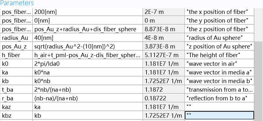
With the above derivation, let’s now set up COMSOL. The first is related variables
| parameters | Value | Description |
|---|---|---|
| WL0 | 532e-9[nm] | |
| k0 | 2*pi/WL0 | |
| n_sub | 1.4607 | |
| n_air | 1 | |
| k1 | k0*n_sub | |
| k2 | k0*n_air | |
| theta_1 | 50/180*pi | |
| theta_2 | conjugate(asin(n_sub*sin(theta_1)/n_air)) | The complex conjugate here comes from the exponential -ikr |
| r | (n_air*cos(theta_1)-n_sub*cos(theta_2))/(n_air*cos(theta_1)+n_sub*cos(theta_2)) | |
| t | 2*n_subcos(theta_1)/(n_air\cos(theta_1)+n_sub*cos(theta_2)) | |
| k1x | k1* sin(\theta_1) | |
| k1z | k1* cos(\theta_1) | |
| k2x | k2* sin(\theta_2) | |
| k2z | k2* cos(\theta_2) | For pure imaginary numbers, add a minus sign to indicate attenuation |
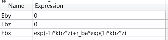
Then there is the background field setting, in the glass layer
| Expression | Value |
|---|---|
| E0x | -cos(theta_1)*exp(-1j*(k1x*x+k1z*z))+r*cos(theta_1)*exp(-1j*(k1x*x-k1z*z)) |
| E0y | 0 |
| E0z | sin(theta_1)*exp(-1j*(k1x*x+k1z*z)) + r*sin(theta_1)*exp(-1j*(k1x*x-k1z*z)) |
In air layer
| Expression | Value |
|---|---|
| E0x | -cos(theta_2)*t*exp(-1j*(k2x*x+k2z*z)) |
| E0y | 0 |
| E0z | sin(theta_2)*texp(-1j\(k2x*x+k2z*z)) |
P-polarized plane waves are incident obliquely with arbitray horizontal angle
Analytical expression
This is to calculate the oblique incidence. When we set it specifically, SiO2 is on the bottom, and the plane wave is incident from the bottom to the top, from the negative X direction to the positive direction with a azimuthal angle $\phi$, Then correspondingly, the incident wave in this coordinate system should be written as,
Note that the $k_{z}$ of the reflected light should become a negative sign, and the relationship between the projected field and the reflected field is
In the glass layer, the total field is the superposition of the incident field and the reflected field, and the sign of different components needs to be considered when superposing.
In the air layer, the total field is the transmitted field
COMSOL Settings Summary
Now I will COMSOL implementations here.