Direction in port-Plane wave input via port in COMSOL
Direction of input wave via port in COMSOL
[TOC]
Introduction
In COMSOL5.1, when we need input the plane wave from port, we need set the field expressions and the phase factors manually. In COMSOL 5.4, the evaluation angel $\alpha{1}$ and azimuthal angle $\alpha{2}$ are introduced to help us define the input angle. However, the definition of the angle combined with the field is not so easy. I spend a lot of time to learn and test the angle and then finally obtain the proper way to define the plane wave input directions via port.
The simulation problem
I follow the example from COMSOL’s library:
Wave Optics Model >Optical Scattering>Scatterer on Substrate
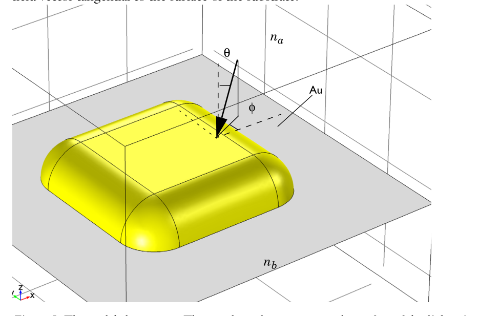
This example analyze the scattering of light by a gold objects on a substrate. A TE polarized light input from z to -z. The most important part is the background field simulations. The background field $E_{b}$ in this example is defined as the field when the gold object is absent. This can be done via two port and four periodic conditions. One port is used to excite the plane wave and the other one is to match the output of the plane waves. Periodic conditions can let the simulation perpendicular to the z infinite. We can also use PML instead but the periodic conditions are better.
The setting in COMSOL5.1 is as follows
we can see that we need specify the wavevector $k{x},k{y},k{z}$ and the field expressions $E=(E{x},E{y},E{z})e^{-i\vec{k}\cdot \vec{r}}$ .
In COMSOL 5.4, we introduce the new evaluation angle $\alpha{1}$ and azimuthal angle $\alpha{2}$ to define the input directions.
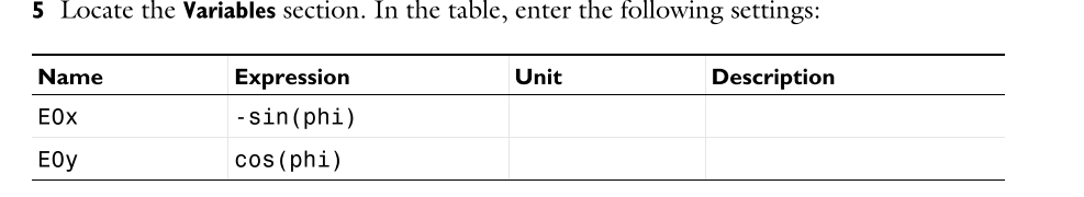
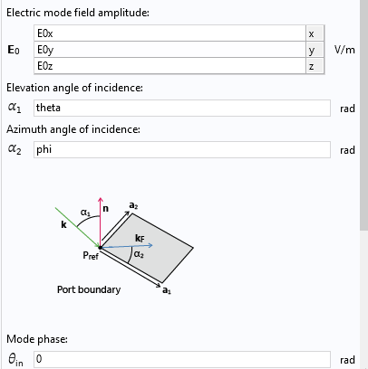
Then we only need specify the field amplitude in ports and the propagation directions can be obtained from $\alpha{1},\alpha{2}$. The problem lies in the settings of field amplitude to match the input directions especially when we want to input a p polarized light or s polarized light or circular polarized light. This is the main point of this note!
Explanation of the incident angle
I searched on the internet to find useful information about the input direction settings, for example
https://www.comsol.com/blogs/modeling-electromagnetic-waves-periodic-structures/
But there is still little useful information. I finally found that we can plot the input wavevector $k{\text{incident}}$ and mode vector $k{\text{mode}}$ which can help us understand the input directions in port.
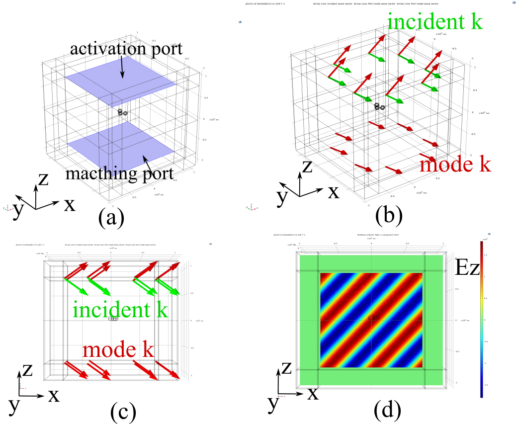
As is shown in above figure. The light input from z to -z and $\alpha{1}=0,\alpha{2}=50^{o}$. The blue arrows show the input wavevector $k{\text{incident}}$ which points into the interior of the simulation domain. However, the mode wavevector $k{\text{mode}}$ which indicates the field’s default wavevector directions on the port points to negative z direction. This is because the normal vector of the port points out the simulation domain and the default wavevector will also point out.
How we define the angle? What is the definition of $\alpha{1},\alpha{2}$? To let it more clear I will show you if you want to define a p polarized light input, how you set the field amplitudes.
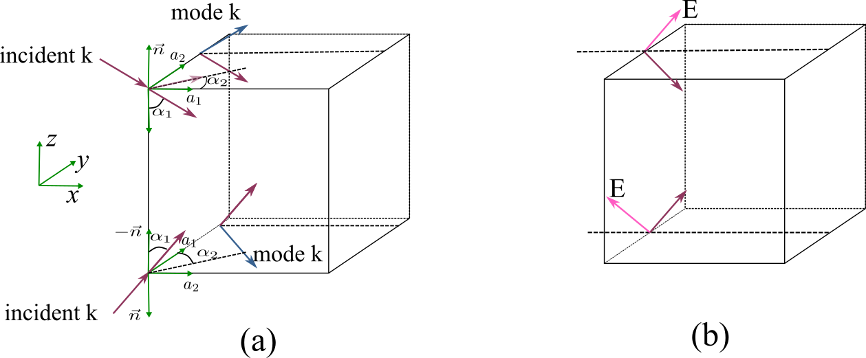
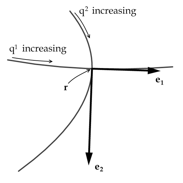
In the port definitions. We introduce a coordinate formed by $(a{1},a{2},n)$ as is shown in Figure (a) above. They satisfy
- $\alpha{1}$ is the angle between incident $k{\text{incident}}$ and the minus normal vector $-n$. And $0<\alpha_{1}<=\pi/2$.
- $\alpha{2}$ is the angle between incident $k{\text{incident}}\sin(\alpha{1})$ (its projection in x-y plane) and the minus normal vector $a{1}$. And $0<\alpha{2}<=2\pi$. The positive direction of $\alpha{2}$ is the angle points to $a_{2}$.
- The mode wavevector $k{\text{mode}}$ is the wavevector has a angle $\alpha{1}$ with $n$ and a angle $\alpha{2}$ with $k{\text{incident}}sin(\alpha_{1})$ too.
- If the light input from $z$ to $-z$, $a{1}$ points positive x and $a{2}$ points positive $y$. $n$ points negative $z$.
- If the light input from $-z$ to $z$, $a{2}$ points positive x and $a{1}$ points positive $y$. $n$ points negative $z$.
- The field should be defined according to the mode wavevector on the port.
Input from z to -z
Then if we want to define a p polarized light input from z to -z. The incident wavevector is
the corresponding mode vector is
and the field amplitude should be defined according to $k_{\text{incident}}$. Then
Input from -z to z
And if we want to define a p polarized light input from -z to z. The incident wavevector is
the corresponding mode vector is
and the field amplitude should be defined according to $k_{\text{incident}}$. Then
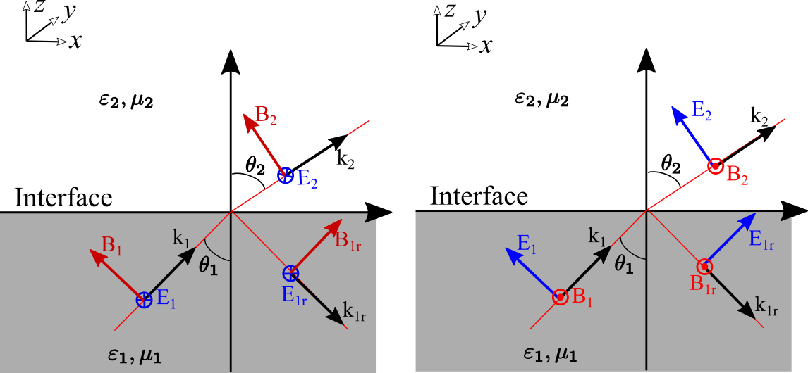
These definitions let our electric field be p polarized light. If we make some small errors on the sign, the results will be different.
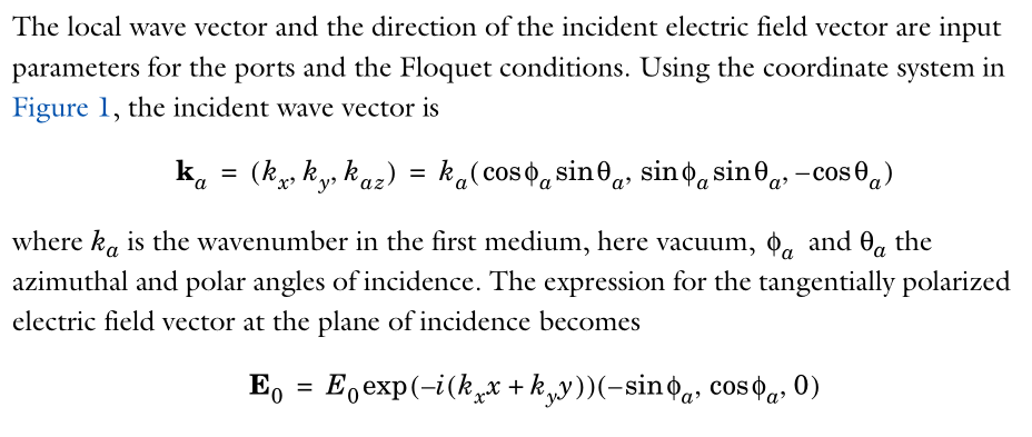
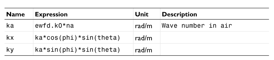
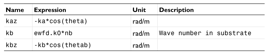
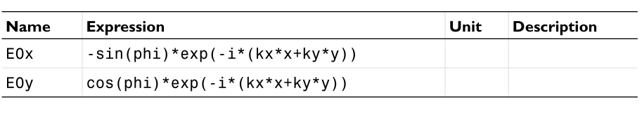
I verify this settings according to the theoretical background settings.